Series circuits
Series circuits A circuit and circuit diagram containing a cell and two lamps connected in series. If you look at the image above, the cell and both lamps are on the same wire loop. You can put more components on the series circuit, but they have to be on the same loop as the others. The component you add on does not have to be a lamp, it can be any other component like a motor. Note: Switches can be added to a series circuit to turn components on and off. If a switch is open in a series circuit, then current will stop flowing and all the components will stop working. Disadvantages of series circuits Current and resistance in series circuits As the current is the same in all parts of the circuit, the reading is the same on all three ammeters (3 A).
A series circuit is a circuit where all the components are on the same loop. Below is an example of a series circuit diagram: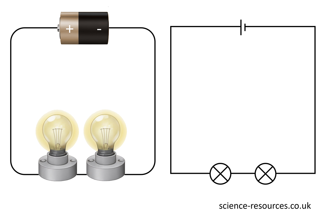
The current in a series circuit changes with the number of cells. The more cells you have, the more current there will be.
One problem with series circuits is that when a component stops working, it breaks the circuit. This means the other components will stop working too.
In the series circuit diagram above, both lamps are on because all components are working well. But, if one of the lamps stops working, it will break the whole circuit and none of the lamps will be on.
It does not matter which component stops working in a series circuit, as all components are on the same loop. So, when one component stops working, the other components will not work either.
A series circuit has the same current everywhere. It does not matter where you put the ammeter, it will show you the same current.
In the diagram below, the circuit has a cell, two lamps and three ammeters. The current is the same for all the ammeters, because there is only one way for the current to go.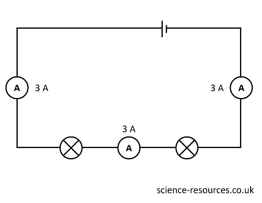
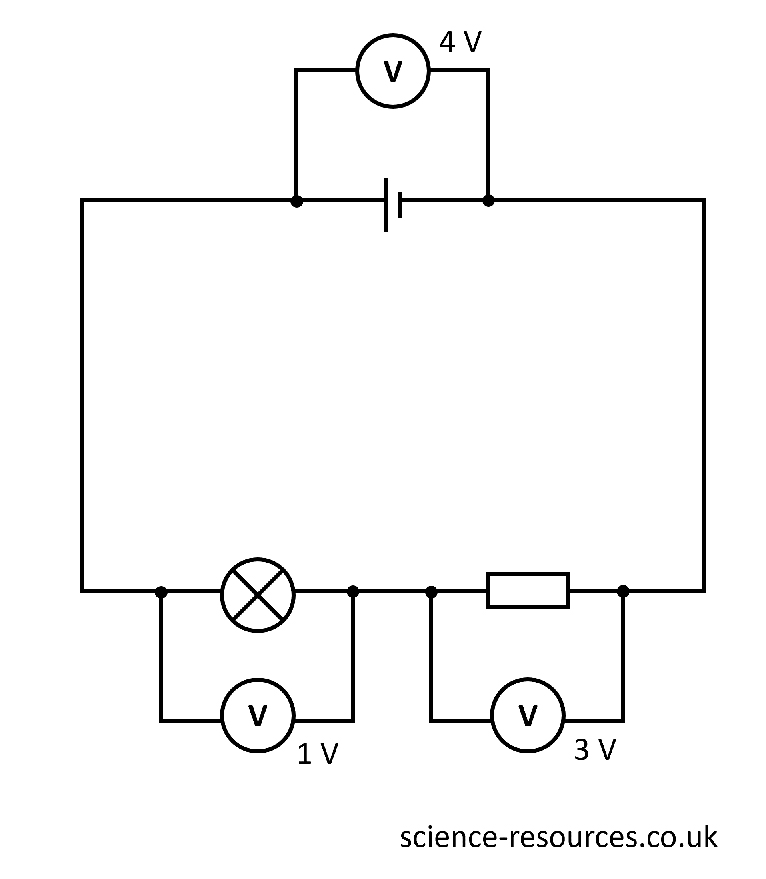
Adding components in series By adding a second lamp to a series circuit, the resistance is increased so the current is lower and the lamps are dimmer. Potential Difference in a Series Circuit In the diagram above, we can see the potential difference the cell provides is 4 V. As we have two of the same components (two lamps) the potential difference is shared equally between the two lamps. The 2 V across the two lamps adds up to the 4 V provided by the cell. Let’s look at a series circuit diagram with different components. The diagram above includes has two different components (a lamp and a resistor). As a result, the potential difference provided by the cell may be distributed unequally. In this case, the potential difference across the lamp is 1 V and the potential difference across the resistor is 3 V.
A series circuit has more resistance when you add more components, so the current goes down.
In the diagram below, the circuit on the left has a lamp, a cell, a switch, and an ammeter. The current is 6 A. The circuit on the right has two lamps, a cell, a switch, and an ammeter. The two lamps have more resistance than one lamp, so the current is lower. The ammeter shows 3 A. This means the lamps are less bright.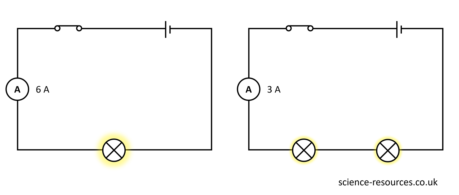
The potential difference produced by a cell or battery is shared between components in a series circuit. This means that the sum of the potential differences across all components is equal to the potential difference of the cell or battery.
We use a voltmeter to measure the potential difference. Potential difference is measured in volts (V).
In a series or a parallel circuit, the voltmeter is not in the same loop as the other components. Instead, it is across the component you are measuring, connecting a wire to both sides of the component you are measuring. You can see this in the series circuit diagram below: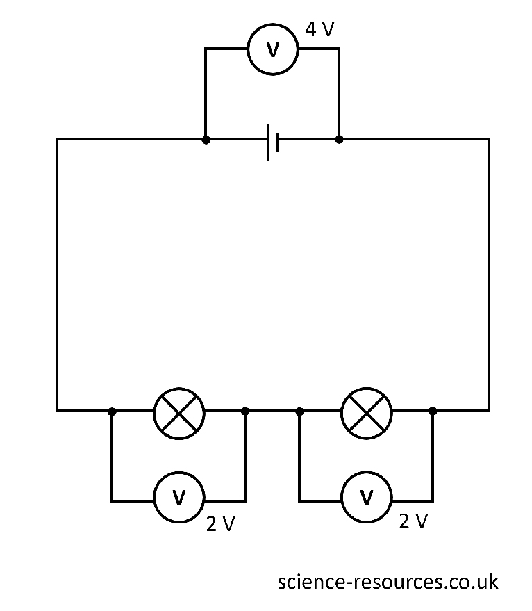
Summary: